IEC 61347-2-8 Special requirements for high voltage impulse test sets for ballasts for fluorescent lamps explained
Fluorescent lamp ballasts play a key role in regulating and controlling the flow of current in fluorescent lamps. They are responsible for providing the required voltage and current to start and maintain the operation of fluorescent lamps. To ensure the fluorescent lighting systems are safe and reliable, high voltage pulse testing of fluorescent lamp ballasts is required.

According to IEC 61347-2-8-2006. Lamp controlgear - Part 2-8. Part 2-8. Particular requirements for ballasts for fluorescent lamps Lamp controlgear - Part 2-8: Particular requirements for ballasts for fluorescent lamps for 50 Hz or 60 Hz AC power supply up to 1000V. Special requirements (excluding resistive ballasts).
According to Article 15.1 of the High Voltage Pulse Test, six samples are taken according to 5.1, and three samples are used to carry out the moisture resistance test and electrical strength test specified in Chapters 11 and 12.
The remaining three ballasts are placed in an oven and heated until they reach the tw temperature values indicated on the ballasts.
Immediately after completion of these pretreatment tests, all six samples were subjected to the high voltage pulse test.
The test ballasts [together with a variable resistor and a suitable relay switch, e.g. H16 or vacuum switch type VR/312/412, with a closing time (excluding bounce time) of 3 ms 15 ms, are connected to a DC power supply so as to allow the ballasts to reach the tw temperature marked on the ballasts.
The DC power supply is connected so that the voltage pulse can be bowed in the ballast by regulating the current and operating the line relay, then the current is slowly regulated and raised until the peak voltage signalled by the ballast is reached. The voltage is then slowly adjusted and increased until the peak voltage signalled by the ballast is reached. Measurement of the pulse voltage should be made directly at the ballast terminals in accordance with Appendix I and Figure I.1.
Note 1: If electronic relays with very short closing times are used, care should be taken to prevent particularly high induced pulse voltages.
Make a note of the DC current value at which the starting voltage is reached, then operate the ballast at this current for 1lh, during which time the current is disconnected 10 times per minute, each time for 3s.
Immediately after completion of this test, all six ballasts shall be subjected to the moisture-proof insulation and dielectric strength tests specified in Chapters 11 and 12.
Note 2: For test circuits with series capacitors, short-circuit the capacitors. short-circuit the capacitors.
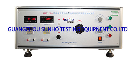
The SH3329A Ballast Pulse Tester for Lamps with Integral Starter is designed to perform pulse endurance tests on simple inductive ballasts in accordance with the requirements of IEC 61347-2-8-2006, Clause 15.1, Appendix I and Figure I.1. It adopts vacuum relay switching, which is stable and reliable.
Technical parameters: 1.
1、Operating voltage: AC 220V/50Hz.
2, test voltage output: 0 60V adjustable.
3、Test time: 0.1~99H adjustable.
4, pulse interval time: 1 99S can be set.
5、Voltage Sensitive Resistor: 100~1000V, 100V increment; 1K~6KV, 1KV increment.
6、R1: 0~100Ω 1A;R2: 0~1KΩ 1A.
7, Voltmeter: 0 ~ 300V, accuracy ± 1.5%; Ammeter: 0 ~ 3A, accuracy ± 1.5%;.
8, working temperature / humidity: temperature 20 ± 5C; humidity 60%.


