Abstract: The scorching wire test is widely used in lighting products, home appliances and material analysis. Based on years of accumulated experience in laboratory testing work, the author of this paper summarises the many factors that affect the results of the scorching wire test with reference to the basic standards of the scorching wire test and the requirements of the safety standards for lamps and lanterns, and summarises the matters that should be noted during the scorching wire test to improve the technical level. Keywords: luminaire product safety; scorch wire test; thermocouple residues; influencing factors
Abstract: The glow wire test in lighting products, household electrical appliances, materials widely used analysis, the author based on many years'accumulation of working experience in laboratory testing, referring to the glow wire test basic standards and safety standards of lighting, summarize the many factors influencing the glow wire results, and summarize the glow wire test items that should be paid attention in the process, improve Keywords: lighting product safety; glow-wire test; thermocouple residue; influence factors.
The scorching wire test is a technical assessment of the risk of a product catching fire by simulating the effects of heat stress on the surrounding components from a heat source such as an overheated component or an overloaded resistor in a short period of time. The test is covered by many electrical and electronic safety standards, such as Chinese National Standard GB7000.1 "General Safety Requirements for Lamps and Lighting" (IEC60598-1), GB4706.1 "General Safety Requirements for Household Appliances", and the International Electrotechnical Commission (IEC60598-1). (The importance of this standard can be seen in the safety standards GB2099.1/IEC60884 for sockets, IEC60335, etc.
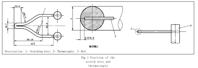
This article analyses in detail the factors influencing the test results and the precautions to be taken during the scorching wire test in conjunction with the requirements of GB7000.1. 1 Impact of test equipment installations 1-1 Scorching wire The temperature value of the scorch wire is measured using a thin armoured thermocouple wire of 0.5 mm diameter, which is mounted in a pre-drilled hole in the top of the wire, see detail Z below. The thermocouple should ensure that it is mounted in place and that a distance of 0.6 mm ± 0.2 mm ± is maintained between the top of the thermocouple and the top of the wire as required by the standard. When the top of the thermocouple is further away from the bottom of the borehole, the actual temperature at the top of the wire will be higher than the temperature indicated by the thermocouple. Although most laboratories use the "silver foil method" for self-calibration, the actual temperature of the top of the thermocouple is higher than that indicated by the thermocouple at the end of each test.
The accuracy of the test results will be directly affected by the need to use a wire brush to clean the residue from the top of the scorch wire if the testers do not operate properly, i.e. it is easy to cause the thermocouple to deviate from the position at the bottom of the scorch wire hole. The laboratory should develop appropriate precautions, such as a reasonable frequency of self-calibration of the scorch wire temperature and detailed precautions for the cleaning process, to avoid poor contact between the thermocouple and the top of the scorch wire. Scorch wire diameter: 4.0mm ± 0.07mm (before bending), this size needs to be measured before each measurement, if it is out of tolerance the scorch wire head needs to be replaced.
The standard for the scorch wire test states that the test should be carried out without air convection and that the chamber should have an internal volume of at least 0.5m3 to facilitate observation of the test sample and the test results and to ensure that the loss of oxygen in the air during the test does not significantly affect the test results. The standard also specifies that the interior surface of the test chamber should be dark enough to allow the illuminance of less than 20lx on the surface of the chamber when the illuminance meter is facing the test sample, because the flame produced during the scorching wire test is relatively small and cannot be easily observed by the tester when the background is too bright; only when the test background is dark enough can the tester easily observe the flame height and scale etc. However, to facilitate cleaning and finishing after the test, many test chambers are equipped with a light, and the laboratory should ensure that the operator turns this light off during the test.
The standard requires that the heating circuit of the scorch wire must not have a feedback device or feedback loop to maintain the temperature value, as shown in Figure 2 below, which is a simple circuit where the power supply for the device should be
A stable voltage source (±2%rms). The test circuit should contain a current measuring device which indicates the true RMS value within a maximum error of 1% and whose control voltage or current value cannot be readjusted until the end of the test. Due to the high currents involved, all electrical connections to the scorch wire must be capable of carrying the appropriate currents without affecting their performance or the stability of the circuit over time. As the scorch wire is set on the connection points, a sufficient contact area (generally not less than 60 mm2 per end) is necessary for a stable non-destructive current and for the test itself. Care should be taken and ensured that the screws between the scorch wire and the connection points are locked or copper soldered to avoid excessive contact resistance from loosening and resulting in deviations from the temperature control accuracy. When the sample or part touches the wire, the temperature of the wire decreases and then increases significantly. Statistically, the temperature of the wire is about 100°C lower than the set value at the moment of contact and then rises by about 20°C. It is therefore wrong to use equipment with a temperature regulation device to maintain a stable temperature or to manually adjust the temperature during the test to compensate for this, as this leads to tighter test conditions and affects the correctness of the test results. The laboratory should take steps to remove automatic temperature regulation devices and prohibit the test operator from manually adjusting the temperature during the process.
The laboratory can set a reasonable interval for the silver foil calibration according to the frequency of the daily tests. In addition, as the silver foil check will cause some wear and tear on the top of the scorch wire, it is not advisable to carry out this check as often as possible. The laboratory can reasonably set the periodicity of the silver foil check according to the frequency of the daily tests, which I recommend should be carried out at least once every 1-2 months. Heating current and corresponding The temperature can be plotted as a relationship curve as shown in Fig. 3. The heating current values calculated from the relationship curve can be used to set the temperature of the scorch wire in a test or calibration. The curve can be used as long as the heating current value is within 2% of the medium heating current value corresponding to the temperature of the scorch wire in the curve. If the heating current value is not within this range or if the scorch wire is replaced, the scorch wire unit should be checked and pre-pr


